PL
EN
DE
RU
Plastic processing with use of injection molding technology
Plastic injection molding is a complex technological process realised by multifunctional, modern machines. All types of those devices have similar (Fig. 1.1 i Fig. 1.3) structure, as they consist of functional units responsible for controlling and regulation, drive, closing and opening of the form and injection. Depending on the type of plastic being processed, way of work, form type etc. they are adjusted to fulfil requirements of specific technological variants in a constructional way, or by do application of special technical equipment. Dimensions of the injection molding machine and it’s production possibilities are specified by the closing force, injection volume and dimensions of the space where the mold is mounted.
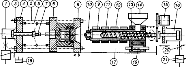
Fig. 1.1 Construction scheme of screw injection molding machine with basic units [1]: 1- table drive servomotor, 2- table-leading columns, 3- nuts used to fix table height, 4- back table, still, inverted, 5- unit column- lever, 6- mobile table, 7- injection molding bumper, 8- front still table, 9- injection molding cylinder, 10- nozzle, 11- screw, 12- heater, 13- cylinder charging zone cooling, 14- hopper, 15- drive motor for rotating the screw, 16- servomotor of screw mobility, 17- injection unit fences, 18- oil tank of the hydraulic system, 19- servomotor of cylinder mobility, 20- suppressor, 21- regulator
The process of plastic injection molding depends on termo-mechanical plasticising of plastic granulate given by hopper(Fig. 1.6) into a pre-heated (up to specific for heating zones values) cylinder of injection molding machine (Fig. 1.7), then injecting it (Fig. 1.5) in strictly-defined conditions (pressure, temperature, volume) with appropriate use of injection unit functions (Fig. 1.4) into a special tool, mounted on the injection machine, know as injection mold (Fig. 1.5). Injected plastic fills the forming sockets of thermostaded injection mold and after pre-defined crystalisation time (cooling) changes its form from liquid into solid, becoming a formed moulded piece. During the cooling period the plastification function starts (Fig. 3.6), filling the cylinder back while plasticising the plastic with use of rotating screw movement in the plastification unit. Fully formed moulded piece is released from the molding form by the closing unit movement (Fig. 1.8), being the mold opening function, and ejecting unit that releases the element from mold with use of molds inner ejector tools. (Fig. 1.9) Closing unit then closes again and the process becoming cyclical.
Precisely setting and monitoring process parameters during the process ensures the repeatability of elements.
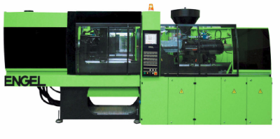
Fig. 1.2 View of a modern Engel injection molding machine.
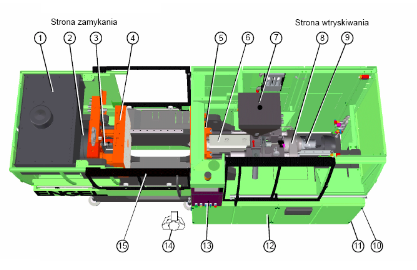
Fig. 1.3 Scheme of ENGEL VICTORY injection molding machine, example: VC 330/80 TECH: 1- hydraulic oil tank, 2- closing cylinder, 3- hydraulic ejector, 4- mobile plate used for mold attaching, 5- still plate used for mold attaching, 6- plastification cylinder with cylinder with nozzle, 7- hopper, 8- injection unit, 9- dosage screws drive, 10- main switch, 11- mains socket, 12- control panel box, 13- control panel with screen, 14- workplace for person operating the machine, 15- mobile security cover
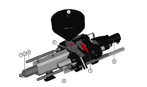
Fig. 1.4 Main assemblies of injection unit [2]: 1- hopper, 2- electrically heated nozzle, 3- electrically heated cylinder, 4- mounted wedging on machines frames, 5- cooled zone of power (traverse) with thermometer, 6- screw position indicator, 7- hydraulic injection cylinder, 8- screw drive hydraulic engine
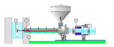
Fig. 1.5 Process of injecting plastic into the mold [2]: 1- inner pressure of mold, 2- specific pressure of injection, 3- hydraulic pressure of injection, 4- screw valve
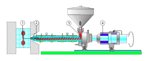
Fig. 1.6 Plastic dosing process [2]: 1- filled socket, 2- screw zone filled with liquid material (specific plastification pressure), 3- material filling hole, 4- hydraulic stacking pressure
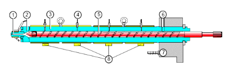
Fig. 1.7 Cylinder [2]: 1- nozzle, 2- collar, 3- cylinder, 4- termosensor, 5- screw, 6- filling hole, 7- traverse with cooling, 8- heating bands
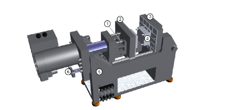
Fig. 1.8 Main assemblies of columnless closing unit [2]: 1- ejector, 2- mobile mounting plate, 3- still mounting plate, 4- form, 5- frame, 6- closing cylinder
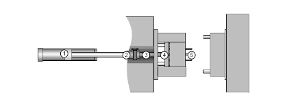
Fig. 1.9 Ejector unit [2]: 1- hydraulic cylinder, 2- ejector clutch, 3- molds central ejector, 4- ejectors plate, 5- ejectors bolts
Elements time of injection process depends on:
Taking above factors under consideration, cycle time can equal from few seconds (thin-wall elements, i.e. packages) to few minutes (thick-wall technical elements, i.e. for the automotive branch).
Key factor of stabilising the process, and especially providing high quality final products, is precise and effective thermostating injection molds (keeping proper temperature) during the cycle, which makes products of highest quality and best properties.
Literature
[1] Sikora R.: Techniki wytwarzania. Przetwórstwo tworzyw sztucznych, Warszawa 1982
[2] ENGEL VICTORY Injection molding machine manual